Marc's Patented Prototype Example
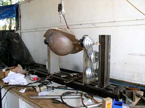
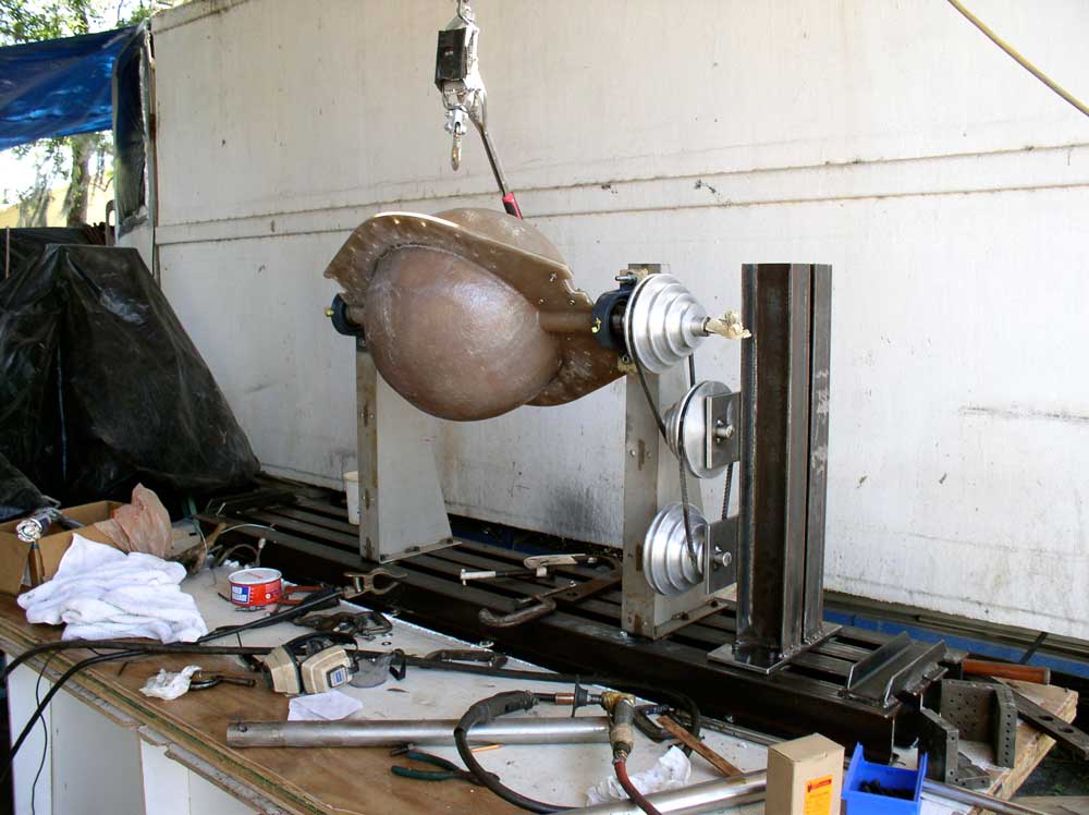
His unique prototype is intended to provide the basic concept for OEM fabricators to build larger and more elaborate versions as production machines. He made his prototype machine from scrap plywood, 1-beams, and miscellaneous equipment laying around his boatyard. The outer shell of the prototype is a 4 x 4 x 8-ft I-beam reinforced vacuum chamber made from several layers of plywood. Inside, a two-piece mold assembly (usually made from fiberglass) bolts together and rotates about an axis. More-complex shapes, such as car bodies, would rotate about two axes.

2018
Step One – Make the plug of the fuselage
To mold an aircraft fuselage, for example, the first step is to make the plug of the fuselage. This entails using a CNC to carve out the shape from special polyester to within 0.0001 in. The next step is to hand lay-up the plug with fiberglass and slit the resulting shape down the middle.
Step Two – Make and insert rubber bladder
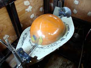
This produces a mold that is the negative of the original shape and smooth on the inside. A rubber bladder (made using slosh molding) is shaped like a fuselage (or any other structure) and is covered with carbon-fiber preform, then placed inside the mold. The bladder could be made the same size as the plug, or slightly smaller. (In the prototype example shown)
Step Three – Produces a mold that is the negative of the original shape
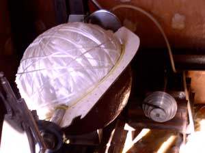
This produces a mold that is the negative of the original shape and smooth on the inside. A rubber bladder (made using slosh molding) is shaped like a fuselage (or any other structure) and is covered with carbon-fiber preform, then placed inside the mold. The bladder could be made the same size as the plug, or slightly smaller. (In the prototype example shown, the rubber ball acted as the bladder.)
Step Four – Marcs composite mold
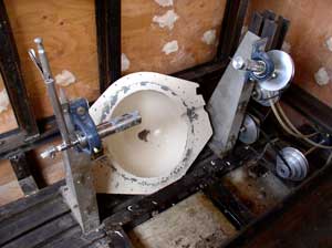
Next comes applying sealant tape between the two mold halves and bolting them together. Then a tiny hole is drilled in the mold. A vacuum pump sucks the air out of the chamber. Users pour resin into the resin reservoir and open the cocks. Due to atmospheric pressure, the resin flows into the mold through tubes in the rotating shaft that holds the mold. The material’s viscosity keeps it from escaping out of the tiny hole (which lets any air between the bladder and the mold escape).
Step Five – Rotate mold
A motor rotates the mold to distribute the resin evenly. The bladder contains air and expands as the vacuum is created. This helps push the carbon fiber-now impregnated with resin – tightly against the inside of the mold for a clamping effect. After the carbon-fiberfuselage sets up, it is removed from the mold. Users can cut out, say, the door, and remove the bladder.
Step Six – Completed single piece monolithic structure
The process could change how composite structures are manufactured because the biggest problem until now has always been the seam. Composite is basically plastic and carbon fiber and bolts can crush the fabric. Also, every time an aircraft flies, the low outside pressure and the higher inside pressure can make the fasteners leak. Most aerospace companies just keep making bigger and bigger composite pieces and bolting them together. No one before has thought to make a large, monolithic structure all in one shot.